| Fire Resistant Cable | |||
![]() Fire Resistant Cable
Fire Resistant Cable
600/1000V Mica+xlPe Insulated, lsZH sheathed Power cables (2-4 cores)FFX400 1mRZ1-R (CU/MGT+XLPE/LSZH 600/1000V Class 2)
|
|||||||||||||||||||||||||||||||||||||||||||||||||||||||||||||||||||||||||||||||||||||||||||||||||||||||||||||||||||||||||||||||||||||||||||||||||||||||||||||||||||||||||||||||||||||||||||||||||||||||||||||||||||||||||||||||||||||||||||||||||||||||||||||||||||||||||||||||||||||||||||||||||||||||||||||||||||||||||||||||||||||||||||||||||||||||||||||||||||||||||||||||||||||||||||||||||||||||||||||||||||||||||||||||||||||||||||||||||||||||||||||||||||||||||||||||||||||||||||||||||||||||||||||||||||||||||||||||||||||||||||||||||||||||||||||||||||||||||||||||||||||||||||||||||||||||||||||||||||||||||||||||||||||||||||||||||||||||||||||||||||||||||||||||||||||||||||||||||||||||||||||||||||||||||||||||||||||||||||||||||||||||||||||||||||||||||||||||||||||||||||||||||||||||||||||||||||||||||||||||||||||||||||||||||||||||||||||||||||||||||||||||||||||||||||||||||||||||||||||||||||||||||||||||||||||||||||||||||||||||||||||||||||||||||||||||||||||||||||||||||||||||||||||||||||||||||||||||||||||||
Circuit Integrity |
IEC 60331-21; BS 6387 CWZ; DIN VDE 0472-814(FE180); |
System circuit integrity |
DIN 4102-12, E30 depending on lay system |
Flame Retardance (Single Vertical |
EN 60332-1-2; IEC 60332-1-2; BS EN 60332-1-2; |
Reduced Fire Propagation |
EN 60332-3-24 (cat. C); IEC 60332-3-24; BS EN 60332-3-24; VDE 0482-332-3; NBN C 30-004 (cat. F2); NF C32-070-2.2(C1); CEI 20-22/3-4; EN 50266-2-4*; DIN VDE 0482-266-2-4 |
Halogen Free |
IEC 60754-1; EN 50267-2-1; DIN VDE 0482-267-2-1; CEI 20-37/2-1 ; BS 6425-1* |
No Corrosive Gas Emission |
IEC 60754-2; EN 50267-2-2; DIN VDE 0482-267-2-2; CEI 20-37/2-2 ; BS 6425-2* |
Minimum Smoke Emission |
IEC 61034-1&2; EN 61034 -1&2; DIN VDE 0482-1034-1&2; CEI 20-37/3-1&2; EN 50268-1&2*; BS 7622-1&2* |
No Toxic gases |
NES 02-713; NF C 20-454 |
Note: Asterisk * denotes superseded standard.
VOLTAGE RATING
600/1000V
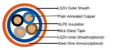
CABLE CONSTRUCTION
Conductor: Plain annealed copper wire, stranded according to IEC(EN) 60228 class 2.
Insulation: Mica glass tape covered by extruded cross-linked XLPE compound
Cabling: The cores are cabled together in concentric layers with suitable non-hygroscopic fillers.
Inner Sheath(optional): Thermoplastic LSZH compound type LTS3 as per BS 7655-6.1
Armouring(optional): Galvanized steel wire armour
Outer Sheath: Thermoplastic LSZH compound type LTS3 as per BS 7655-6.1 (Thermosetting LSZH
compound type SW2-SW4 as per BS 7655-2.6 can be offered.)
COLOUR CODE
Insulation Colour
2 - Core: (Brown & Blue)
3 - Core: (Brown, Black & Grey)
4 - Core: (Brown, Black, Grey & Blue)
Sheath Colour
Orange (other colors upon request)
Physical AND THERMAL PROPERTIES
Temperature range during operation (fixed state): -30°C – +90°C
Temperature range during installation (mobile state): -20°C – +50°C
Minimum bending radius: 8 x Overall Diameter (unarmoured cable)
10 x Overall Diameter (armoured cable)
Electrical PROPERTIES
Dielectric test: |
3500 V r.m.s. x 5' (core/core) |
Insulation resistance |
1000 MΩ x km (at 20°C) |
Short circuit temperature |
250°C |
CONSTRUCTION PARAMETERS
Conductor |
FFX400 1mRZ1-R |
FFX400 1mRMZ1-R | ||||||
No. of Core X Cross Section |
No./ Nominal Diameter of Strands |
Dia. of Conductor |
Nominal
Insulation |
Unarmoured Cable |
Armoured Cable |
|||
Nominal Overall Diameter |
Approx. Weight |
Nominal
Overall |
Approx. |
|||||
No*mm2 |
No./mm |
mm |
mm |
mm |
kg/km |
mm |
kg/km |
|
2 Core |
||||||||
1.5 |
7/0.53 |
1.59 |
0.7 |
12.2 |
150 |
15.3 |
390 |
|
2.5 |
7/0.67 |
2.01 |
0.7 |
12.6 |
180 |
16.5 |
450 |
|
4 |
7/0.85 |
2.55 |
0.7 |
14.7 |
250 |
17.6 |
525 |
|
6 |
7/1.04 |
3.12 |
0.7 |
16.2 |
290 |
18.8 | 620 |
|
10 |
7/1.35 |
4.05 |
0.7 |
17.1 |
450 |
21 | 800 |
|
16 |
7/1.70 |
5.1 |
0.7 |
19.2 |
550 |
23 | 1100 |
|
25 |
7/2.14 |
6.42 |
0.9 |
20 |
680 |
27 | 1480 |
|
35 |
19/1.53 |
7.65 |
0.9 |
22 |
940 |
30 | 2000 |
|
50 |
19/1.78 |
8.9 |
1 |
24 |
1250 |
33 | 2450 |
|
70 |
19/2.14 |
10.7 |
1.1 |
27 |
1700 |
37 | 3200 |
|
95 |
19/2.52 |
12.6 |
1.1 |
31 |
2300 |
42 | 4350 |
|
120 |
37/2.03 |
14.21 |
1.2 |
36 |
3150 |
48 |
6500 |
|
3-Core |
||||||||
1.5 |
7/0.53 |
1.59 |
0.7 |
12.3 |
170 |
16.5 |
420 |
|
2.5 |
7/0.67 |
2.01 |
0.7 |
13.8 |
200 |
17 |
500 |
|
4 |
7/0.85 |
2.55 |
0.7 |
15.2 |
300 |
18.5 |
600 |
|
6 |
7/1.04 |
3.12 |
0.7 |
16.8 |
380 |
19.8 |
785 |
|
10 |
7/1.35 |
4.05 |
0.7 |
18 |
550 |
22.6 |
1030 |
|
16 |
1/1.70 |
5.1 |
0.7 |
21 |
760 |
25 |
1370 |
|
25 |
7/2.14 |
6.42 |
0.9 |
22 |
960 |
29 |
1900 |
|
35 |
19/1.53 |
7.65 |
0.9 |
24 |
1300 |
32 |
2300 |
|
50 |
19/1.78 |
8.9 |
1 |
28 |
1700 |
35 |
2900 |
|
70 |
19/2.14 |
10.7 |
1.1 |
31 |
2400 |
40 |
4000 |
|
95 |
19/2.52 |
12.6 |
1.1 |
36 |
3250 |
45 |
5400 |
|
120 |
37/2.03 |
14.21 |
1.2 |
38 |
4000 |
49 |
6450 |
|
150 |
37/2.25 |
15.75 |
1.4 |
42 |
5000 |
55 |
8200 |
|
185 |
37/2.52 |
17.64 |
1.6 |
47 |
6100 |
60 |
9800 |
|
240 |
61/2.25 |
20.25 |
1.7 |
52 |
8000 |
68 |
12300 |
|
300 |
61/2.52 |
22.68 |
1.8 |
59 |
9850 |
74 |
14800 |
|
400 |
61/2.85 |
25.65 |
2 |
63 |
13000 |
83 |
17600 |
|
4-Core |
||||||||
1.5 |
7/0.53 |
1.59 |
0.7 |
14.3 |
210 |
16 |
475 |
|
2.5 |
7/0.67 |
2.01 |
0.7 |
15.2 |
270 |
17.8 |
570 |
|
4 |
7/0.85 |
2.55 |
0.7 |
17.2 |
380 |
19.8 |
690 |
|
6 |
7/1.04 |
3.12 |
0.7 |
19 |
440 |
21 |
940 |
|
10 |
7/1.35 |
4.05 |
0.7 |
20.6 |
670 |
23.3 |
1200 |
|
16 |
1/1.70 |
5.1 |
0.7 |
23.6 |
820 |
26.5 |
1400 |
|
25 |
7/2.14 |
6.42 |
0.9 |
26 |
1320 |
30.5 |
2400 |
|
35 |
19/1.53 |
7.65 |
0.9 |
29 |
1730 |
34 |
2800 |
|
50 |
19/1.78 |
8.9 |
1 |
32 |
2300 |
38 |
3500 |
|
70 |
19/2.14 |
10.7 |
1.1 |
38 |
3180 |
44 |
5300 |
|
95 |
19/2.52 |
12.6 |
1.1 |
41.9 |
4370 |
48.5 |
6700 |
|
120 |
37/2.03 |
14.21 |
1.2 |
44 |
5400 |
54 |
8500 |
|
150 |
37/2.25 |
15.75 |
1.4 |
50.8 |
6500 |
59 |
10000 |
|
185 |
37/2.52 |
17.64 |
1.6 |
55 |
8200 |
64.5 |
12200 |
|
240 |
61/2.25 |
20.25 |
1.7 |
60.5 |
10600 |
74 |
15400 |
|
300 |
61/2.52 |
22.68 |
1.8 |
68.5 |
13200 |
82 |
19500 |
|
400 |
61/2.85 |
25.65 |
2 |
76 |
17000 |
92 |
25500 |
|
Electrical PROPERTIES
Conductor Operating Temperature : 90°C
Ambient Temperature : 30°C
FFX400 1mRZ1-R
Current-Carrying Capacities (Amp)
| Nominal Cross Section Area |
Reference Method 4 (enclosed in an conduit insulated wall etc) |
Reference Method 3 (enclosed in conduit on a wall or ceiling, or in trunking) |
Reference Method 1 (clipped direct) | Reference Method 11 (on a perforated cable tray), or Reference Method |
|||
| one 3-core cable or one 4-core cable 3-phase a.c. |
one 2-core cable single phase a.c. or d.c. |
one 3-core cable or one 4-core cable 3-phase a.c. |
one 2-core cable single phase a.c. or d.c. |
one 3-core
cable or one
4-core cable 3-phase a.c. |
one 2-core
cable
single phase
a.c. or d.c. |
one 3-core cable or one 4-core cable 3-phase a.c. | |
1 |
2 |
3 |
4 |
5 |
6 |
7 |
8 |
mm2 |
A |
A |
A |
A |
A |
A |
A |
1.5 |
16.5 |
22 |
19.5 |
24 |
22 |
26 |
23 |
2.5 |
22 |
30 |
26 |
33 |
30 |
36 |
32 |
4 |
30 |
40 |
35 |
45 |
40 |
49 |
42 |
6 |
38 |
51 |
44 |
58 |
52 |
63 |
54 |
10 |
51 |
69 |
60 |
80 |
71 |
86 |
75 |
16 |
68 |
91 |
80 |
107 |
96 |
115 |
100 |
25 |
89 |
119 |
105 |
138 |
119 |
149 |
127 |
35 |
109 |
146 |
128 |
171 |
147 |
185 |
158 |
50 |
130 |
175 |
154 |
209 |
179 |
225 |
192 |
70 |
164 |
221 |
194 |
269 |
229 |
289 |
246 |
95 |
197 |
265 |
233 |
328 |
278 |
352 |
298 |
120 |
227 |
305 |
268 |
382 |
322 |
410 |
346 |
150 |
259 |
334 |
300 |
441 |
371 |
473 |
399 |
185 |
295 |
384 |
340 |
506 |
424 |
542 |
456 |
240 |
346 |
459 |
398 |
599 |
500 |
641 |
538 |
300 |
396 |
532 |
455 |
693 |
576 |
741 |
621 |
400 |
- |
625 |
536 |
803 |
667 |
865 |
741 |
Voltage Drop (Per Amp Per Meter)
Nominal Cross Section Area |
2-core cable d.c. |
2-core cable single-phase a.c |
3-core or 4-core cable 3-phase a.c. |
||||
1 |
2 |
3 |
4 |
||||
mm2 |
mV/A/m |
mV/A/m |
mV/A/m |
||||
1.5 |
31 |
31 |
27 |
||||
2.5 |
19 |
19 |
16 |
||||
4 |
12 |
12 |
10 |
||||
6 |
7.9 |
7.9 |
6.8 |
||||
10 |
4.7 |
4.7 |
4 |
||||
16 |
2.9 |
2.9 |
2.5 |
||||
|
|
r |
x |
z |
r |
x |
z |
25 |
1.85 |
1.85 |
0.16 |
1.9 |
1.6 |
0.14 |
1.65 |
35 |
1.35 |
1.35 |
0.155 |
1.35 |
1.15 |
0.135 |
1.15 |
50 |
0.98 |
0.99 |
0.155 |
1 |
0.86 |
0.135 |
0.87 |
70 |
0.67 |
0.67 |
0.15 |
0.69 |
0.59 |
0.13 |
0.6 |
95 |
0.49 |
0.5 |
0.15 |
0.52 |
0.43 |
0.13 |
0.45 |
120 |
0.39 |
0.4 |
0.145 |
0.42 |
0.34 |
0.13 |
0.37 |
150 |
0.31 |
0.32 |
0.145 |
0.35 |
0.28 |
0.125 |
0.3 |
185 |
0.25 |
0.26 |
0.145 |
0.29 |
0.22 |
0.125 |
0.26 |
240 |
0.195 |
0.2 |
0.14 |
0.24 |
0.175 |
0.125 |
0.21 |
300 |
0.155 |
0.16 |
0.14 |
0.21 |
0.14 |
0.12 |
0.185 |
400 |
0.12 |
0.13 |
0.14 |
0.19 |
0.115 |
0.12 |
0.165 |
FFX400 1mRMZ1-R
Current-Carrying Capacities (Amp)
| Nominal Cross Section Area |
Reference Method 1 (clipped direct) | Reference Method 11 (on a perforated cable tray), or Reference Method |
In single-way ducts | Laid direct in ground | ||||
| one 2-core cable single phase a.c. or d.c. |
one 3-core
cable or one
4-core cable 3-phase a.c. |
one 2-core
cable
single phase
a.c. or d.c. |
one 3-core cable or one 4-core cable 3-phase a.c. | one
2-core
cable single phase a.c. or d.c. |
one 3-core or 4-core cable 3-phase a.c. |
one
2-core
cable single phase a.c. or d.c. |
one 3-core or 4-core cable 3-phase a.c. |
|
1 |
2 | 3 | 4 | 5 |
6 |
7 |
8 |
9 |
mm2 |
A |
A |
A |
A |
A |
A |
A |
A |
1.5 |
27 |
23 |
29 |
25 |
- |
23 |
- |
28 |
2.5 |
36 |
31 |
39 |
33 |
- |
30 |
- |
36 |
4 |
49 |
42 |
52 |
44 |
- |
40 |
- |
48 |
6 |
62 |
53 |
66 |
56 |
- |
50 |
- |
60 |
10 |
85 |
73 |
90 |
78 |
- |
65 |
- |
80 |
16 |
110 |
94 |
115 |
99 |
115 |
94 |
140 |
115 |
25 |
146 |
124 |
152 |
131 |
145 |
125 |
180 |
150 |
35 |
180 |
154 |
188 |
162 |
175 |
150 |
215 |
180 |
50 |
219 |
187 |
228 |
197 |
210 |
175 |
255 |
215 |
70 |
279 |
238 |
291 |
251 |
260 |
215 |
315 |
265 |
95 |
338 |
289 |
354 |
304 |
310 |
260 |
380 |
315 |
120 |
392 |
335 |
410 |
353 |
355 |
300 |
430 |
360 |
150 |
451 |
386 |
472 |
406 |
400 |
335 |
480 |
405 |
185 |
515 |
441 |
539 |
463 |
455 |
380 |
540 |
460 |
240 |
607 |
520 |
636 |
546 |
520 |
440 |
630 |
530 |
300 |
698 |
599 |
732 |
628 |
590 |
495 |
700 |
590 |
400 |
787 |
673 |
847 |
728 |
660 |
560 |
790 |
670 |
Voltage Drop (Per Amp Per Meter)
Nominal Cross Section Area |
2-core cable d.c. |
2 cables, single-phase a.c. |
3 or 4 cables, 3-phase a.c. |
2 cables, |
3 or 4 |
||||
| 1 | 2 |
3 |
4 |
5 | 6 | ||||
mm2 |
mV/A/m |
mV/A/m |
mV/A/m |
mV/A/m |
mV/A/m |
||||
1.5 |
31 |
31 |
27 |
31 |
25 |
||||
2.5 |
19 |
19 |
16 |
19 |
15 |
||||
4 |
12 |
12 |
10 |
12 |
9.7 |
||||
6 |
7.9 |
7.9 |
6.8 |
7.9 |
6.5 |
||||
10 |
4.7 |
4.7 |
4 |
4.7 |
3.9 |
||||
16 |
2.9 |
2.9 |
2.5 |
2.9 |
2.6 |
||||
|
|
r |
x |
z |
r |
x |
z |
|
|
25 |
1.85 |
1.35 |
0.16 |
1.9 |
1.6 |
0.14 |
1.65 |
1.9 |
1.6 |
35 |
1.35 |
1.35 |
0.155 |
1.35 |
1.15 |
0.135 |
1.15 |
1.35 |
1.2 |
50 |
0.98 |
0.99 |
0.155 |
1 |
0.86 |
0.135 |
0.87 |
1 |
0.87 |
70 |
0.67 |
0.67 |
0.15 |
0.69 |
0.59 |
0.13 |
0.6 |
0.69 |
0.61 |
95 |
0.49 |
0.5 |
0.15 |
0.52 |
0.43 |
0.13 |
0.45 |
0.52 |
0.45 |
120 |
0.39 |
0.4 |
0.145 |
0.42 |
0.34 |
0.13 |
0.37 |
0.42 |
0.36 |
150 |
0.31 |
0.32 |
0.145 |
0.35 |
0.28 |
0.125 |
0.3 |
0.35 |
0.3 |
185 |
0.25 |
0.26 |
0.145 |
0.29 |
0.22 |
0.125 |
0.26 |
0.29 |
0.25 |
240 |
0.195 |
0.2 |
0.14 |
0.24 |
0.175 |
0.125 |
0.21 |
0.24 |
0.21 |
300 |
0.155 |
0.16 |
0.14 |
0.21 |
0.14 |
0.12 |
0.185 |
0.21 |
0.19 |
400 |
0.12 |
0.13 |
0.14 |
0.19 |
0.115 |
0.12 |
0.165 |
0.19 |
0.18 |
Note : r = conductor resistance at operating temperature
x = reactance
z = impedance