| Firetox Flame Retardant Cables | |||
![]() Firetox Flame Retardant Cables
Firetox Flame Retardant Cables
300/500V XLPE Insulated, LSZH Sheathed Power Cables (single core)FTX300 05RZ1-R (CU/XLPE/LSZH 300/500V Class 2) |
|||||||||||||||||||||||||||||||||||||||||||||||||||||||||||||||||||||||||||||||||||||||||||||||||||||||||||||||||||||||||||||||||||||||||||||||||||||||||||||||||||||||||||||||||||||||||||||||||
Flame Retardance (Single Vertical |
EN 60332-1-2; IEC 60332-1-2; BS EN 60332-1-2; VDE |
Reduced Fire Propagation |
EN 60332-3-24 (cat. C); IEC 60332-3-24; BS EN 60332-3-24; VDE 0482-332-3; NBN C 30-004 (cat. F2); NF C32-070-2.2(C1); CEI 20-22/3-4; EN 50266-2-4*; DIN VDE 0482-266-2-4 |
Halogen Free |
IEC 60754-1; EN 50267-2-1; DIN VDE 0482-267-2-1; CEI 20-37/2-1 ; BS 6425-1* |
No Corrosive Gas Emission |
IEC 60754-2; EN 50267-2-2; DIN VDE 0482-267-2-2; CEI 20-37/2-2 ; BS 6425-2* |
minimum Smoke Emission |
IEC 61034-1&2; EN 61034 -1&2; DIN VDE 0482-1034-1&2; CEI 20-37/3-1&2; EN 50268-1&2*; BS 7622-1&2* |
No Toxic gases |
NES 02-713; NF C 20-454 |
Note: Asterisk * denotes superseded standard.
VOLTAGE RATING
300/500V
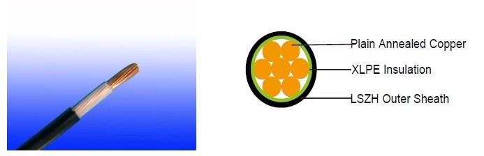
CABLE CONSTRUCTION
Conductor: Plain annealed copper wire, stranded according to IEC(EN) 60228 class 2.
Insulation: Extruded cross-linked XLPE compound.
Outer Sheath: Thermoplastic LSZH compound type LTS3 as per BS 7655-6.1 (Thermosetting LSZH
compound type SW2-SW4 as per BS 7655-2.6 can be offered.)
COLOUR CODE
Insulation colour as per bs7671
|
with earth conductor |
without earth conductor |
2Cores |
- |
Brown,Blue |
3Cores |
Yellow/Green,Brown,Blue |
Brown,Gray,Black |
4Cores |
Yellow/Green,Brown,Gray,Black |
Brown,Gray,Black,Blue |
5Cores |
Yellow/Green,Brown,Gray,Black,Blue |
Brown,Gray,Black,Blue,Black |
above 5 Cores |
Yellow/Green,Black Numbered |
Black Numbered |
sheath colour: Black
Physical AND THERMAL PROPERTIES
Temperature range during operation: Max.90°C for XLPE
250°C in short-circuit for 5s max.
Minimum bending radius: 6 x Overall Diameter (unarmoured cable)
10 x Overall Diameter (armoured cable)
SWB Steel wire braid
CONSTRUCTION PARAMETERS
Conductor |
FTX300 05RZ1-R |
|||
No. of Core X Cross Section |
No./Nominal |
Nominal |
Nominal |
Approx. Weight |
Noxmm2 |
No./mm |
mm |
mm |
kg/km |
1x1.5 |
7/0.53 |
0.50 |
3.8 |
27 |
1x2.5 |
7/0.67 |
0.50 |
4.2 |
37 |
1x4.0 |
7/0.85 |
0.50 |
4.8 |
54 |
Electrical PROPERTIES
Conductor Operating Temperature : 90°C
Ambient Temperature : 30°C
Current-Carrying Capacities (Amp)
| Conductor crosssectional area
|
Reference Method 4 (enclosed in conduit in thermally insulating wall etc) |
Reference Method 3 (enclosed in conduit on a wall or in trunking etc) |
Reference Method 1 (clipped direct) |
Reference Method 11 (on a perforated cable tray, horizontal or vertical) |
Reference Method 12 (free air) |
||||||
| Horizontal flat spaced |
Vertical flat spaced |
Trefoil | |||||||||
2 cables, single- phase a.c. or d.c. |
3 or 4 cables, |
2 cables, single- phase a.c. or d.c |
3 or 4 cables, |
2 cables, single- phase a.c. or d.c. flat and touching |
3 or 4 cables, |
2 cables, single- phase a.c. or d.c. or flat and touching |
3 or 4 cables, |
2 cables, single- phase a.c. or d.c. |
2 |
3 cables, trefoil |
|
1 |
2 |
3 |
4 |
5 |
6 |
7 |
8 |
9 |
10 |
11 |
12 |
mm2 |
A |
A |
A |
A |
A |
A |
A |
A |
A |
A |
A |
1.5 |
18 |
17 |
22 |
19 |
25 |
23 |
- |
- |
- |
- |
- |
2.5 |
24 |
23 |
30 |
26 |
34 |
31 |
- |
- |
- |
- |
- |
4 |
33 |
30 |
40 |
35 |
46 |
41 |
- |
- |
- |
- |
- |
Voltage Drop (Per Amp Per Meter)
| Nominal Cross Section Area |
2 cables d.c. |
2 cables, single-phase a.c. | 3 or 4 cables, 3-phase a.c. | |||
| Ref. Methods 3 and 4 (enclosed in conduit etc, in or on a wall) |
Ref. Methods 1 and 11 (clipped direct or on trays touching) |
Ref. Methods 3 and 4 (enclosed in conduit etc, in or on a wall) |
Ref. Methods 1, 11 and 12 (in trefoil) |
Ref. Methods 1 and 11(Flat and touching) |
||
1 |
2 |
3 |
4 |
5 |
6 |
7 |
mm2 |
mV/A/m |
mV/A/m |
mV/A/m |
mV/A/m |
mV/A/m |
mV/A/m |
1.5 |
31 |
31 |
27 |
27 |
27 |
27 |
2.5 |
19 |
19 |
16 |
16 |
16 |
16 |
4 |
33 |
12 |
10 |
10 |
10 |
10 |