| Industrial Cables | |||
 Australian Standard (Medium Voltage)
6.35/11kV Single Core Screened & PVC Sheathed (Al Conductor)
Application
6.35/11kV Single Core Screened & PVC Sheathed (Al Conductor) cables are designed to be used for the supply of electrical energy in fixed applications up to the rated voltages at a nominal power frequency between 49Hz and 61Hz., 6.35/11kV Single Core Screened & PVC Sheathed (Al Conductor) cables are suitable for use in distribution installation, electrical power station , they are applied for installation, outdoors, underground where subject to mechanical damage.
Standard
AS/NZS 1429.1
Cable Construction
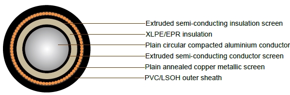
CONDUCTOR: Plain circular compacted aluminium to AS/NZS1125 Maximum Continuous Operating Temperature: 90°C
CONDUCTOR SCREEN: Extruded semiconducting compound, bonded to the insulation and applied in the same operation as the insulation
INSULATION: Cross Linked Polyethylene (XLPE) – standard Ethylene Propylene Rubber (EPR) – alternative
INSULATION SCREEN: Extruded semiconducting compound
METALLIC SCREEN: Plain annealed copper wire: 3kA for nominal 1 second(LIGHT DUTY) Plain annealed copper wire: 10kA for nominal 1 second(HEAVY DUTY)
SHEATH: Black 5V90 polyvinyl chloride (PVC) – standard
Orange 5V90 PVC inner plus black high density polyethylene (HDPE) outer – alternative Low smoke zero halogen (LSOH) – alternative
Technical Characteristics
LIGHT DUTY
| Nominal cond uctor area |
Maximum Cond uctor DC resist ance at 20°C |
Cond. AC resistance at 50Hz and 90°C | Inductive reactance at 50Hz and 90°C | Insulation resistance at 20°C | Conductor to screen capac itance |
Maximum diaelectric stress | Current Ratings | |||||
| Trefoil or Flat touc hing |
flat spaced | Trefoil touc hing |
flat touch ing |
flat spaced | Unen closed In Air |
Buried Direct | Buried In Ducts (c) | |||||
| mm2 | Ohm/km | Ohm/km | Ohm/km | Ohm/km | Ohm/km | Ohm /km |
MegOhm. km | µF x km | kV x mm | A | A | A |
| 35 | 0.868 | 1.11 | 1.11 | 0.144 | 0.159 | 0.205 | 11000 | 0.22 | 2.54 | 153 | 142 | 119 |
| 50 | 0.641 | 0.821 | 0.821 | 0.14 | 0.155 | 0.201 | 9900 | 0.243 | 2.46 | 184 | 167 | 140 |
| 70 | 0.443 | 0.568 | 0.568 | 0.129 | 0.145 | 0.19 | 8700 | 0.276 | 2.37 | 229 | 204 | 172 |
| 95 | 0.32 | 0.41 | 0.41 | 0.123 | 0.138 | 0.184 | 7800 | 0.311 | 2.3 | 279 | 243 | 205 |
| 120 | 0.253 | 0.325 | 0.325 | 0.118 | 0.134 | 0.179 | 7100 | 0.339 | 2.25 | 322 | 276 | 237 |
| 150 | 0.206 | 0.265 | 0.264 | 0.115 | 0.13 | 0.176 | 6600 | 0.368 | 2.22 | 365 | 309 | 265 |
| 185 | 0.164 | 0.211 | 0.211 | 0.112 | 0.127 | 0.172 | 6100 | 0.398 | 2.18 | 421 | 349 | 300 |
| 240 | 0.125 | 0.161 | 0.161 | 0.107 | 0.123 | 0.168 | 5400 | 0.445 | 2.14 | 499 | 404 | 347 |
| 300 | 0.1 | 0.13 | 0.129 | 0.105 | 0.12 | 0.166 | 4900 | 0.491 | 2.11 | 572 | 455 | 399 |
| 400 | 0.0778 | 0.102 | 0.101 | 0.101 | 0.116 | 0.162 | 4400 | 0.548 | 2.08 | 669 | 519 | 456 |
| 500 | 0.0605 | 0.0803 | 0.079 | 0.097 | 0.112 | 0.158 | 3900 | 0.62 | 2.05 | 779 | 590 | 518 |
| 630 | 0.0469 | 0.0636 | 0.062 | 0.095 | 0.11 | 0.156 | 3500 | 0.695 | 2.02 | 907 | 669 | 587 |
| 800 | 0.0367 | 0.0516 | 0.0494 | 0.092 | 0.107 | 0.153 | 3100 | 0.782 | 2 | 1050 | 752 | 687 |
Cable Parameter
LIGHT DUTY
| Sectional Area of Conductor | Nom. Conductor Diameter | Nom. Insulation Thickness | Nom. Diamete Over insulation | Screen Area on Each core | No. and Diamter of Screened Wires | Nom. Diamete Over Screened Wires | Nom. Overall Diameter | Approx. mass |
| mm2 | mm | mm | mm | mm2 | no x mm | mm | mm | kg/100m |
| 35 | 6.9 | 3.4 | 14.9 | 20 | 36 x 0.85 | 16.3 | 22.5 | 62 |
| 50 | 8.1 | 3.4 | 16 | 20 | 36 x 0.85 | 17.5 | 23.7 | 68 |
| 70 | 9.6 | 3.4 | 17.6 | 20 | 36 x 0.85 | 19.0 | 25.2 | 78 |
| 95 | 11.4 | 3.4 | 19.3 | 20 | 36 x 0.85 | 20.7 | 26.9 | 89 |
| 120 | 12.8 | 3.4 | 20.7 | 20 | 36 x 0.85 | 22.1 | 28.3 | 99 |
| 150 | 14.2 | 3.4 | 22.1 | 20 | 36 x 0.85 | 23.5 | 29.7 | 109 |
| 185 | 15.7 | 3.4 | 23.6 | 20 | 36 x 0.85 | 25.2 | 31.4 | 123 |
| 240 | 18 | 3.4 | 25.9 | 20 | 36 x 0.85 | 27.6 | 33.8 | 145 |
| 300 | 20.1 | 3.4 | 28.3 | 20 | 36 x 0.85 | 29.6 | 36.0 | 168 |
| 400 | 23 | 3.4 | 31.1 | 20 | 36 x 0.85 | 32.7 | 39.3 | 202 |
| 500 | 26.5 | 3.4 | 34.7 | 20 | 36 x 0.85 | 35.8 | 42.6 | 239 |
| 630 | 29.9 | 3.4 | 38.4 | 20 | 36 x 0.85 | 39.4 | 46.4 | 289 |
| 800 | 34.2 | 3.4 | 42.8 | 20 | 36 x 0.85 | 44.0 | 51.3 | 351 |
Technical Characteristics
HEAVY DUTY
| Nominal cond uctor area |
Maximum Conductor DC resist ance at 20°C |
Cond. AC resistance at 50Hz and 90°C | Inductive reactance at 50Hz and 90°C | Insulation resistance at 20°C | Conductor to screen capac itance |
Maximum diaelectric stress | Current Ratings | |||||
| Trefoil or Flat touch ing |
flat spaced | Trefoil touc hing |
flat touch ing |
flat spaced | Unenc losed In Air |
Buried Direct | Buried In Ducts (c) | |||||
| mm2 | Ohm/km | Ohm/km | Ohm/km | Ohm/km | Ohm /km |
Ohm /km |
MegOhm. km | µF x km | kV x mm | A | A | A |
| 35 | 0.868 | 1.11 | 1.11 | 0.144 | 0.159 | 0.205 | 11000 | 0.22 | 2.54 | 153 | 142 | 119 |
| 50 | 0.641 | 0.821 | 0.821 | 0.14 | 0.155 | 0.201 | 9900 | 0.243 | 2.46 | 185 | 168 | 141 |
| 70 | 0.443 | 0.568 | 0.568 | 0.129 | 0.145 | 0.19 | 8700 | 0.276 | 2.37 | 229 | 204 | 172 |
| 95 | 0.32 | 0.41 | 0.41 | 0.123 | 0.138 | 0.184 | 7800 | 0.311 | 2.3 | 281 | 243 | 205 |
| 120 | 0.253 | 0.325 | 0.325 | 0.118 | 0.134 | 0.179 | 7100 | 0.339 | 2.25 | 323 | 275 | 236 |
| 150 | 0.206 | 0.265 | 0.264 | 0.115 | 0.13 | 0.176 | 6600 | 0.368 | 2.22 | 366 | 307 | 263 |
| 185 | 0.164 | 0.211 | 0.211 | 0.112 | 0.127 | 0.172 | 6100 | 0.398 | 2.18 | 420 | 346 | 297 |
| 240 | 0.125 | 0.161 | 0.161 | 0.107 | 0.123 | 0.168 | 5400 | 0.445 | 2.14 | 496 | 399 | 342 |
| 300 | 0.1 | 0.13 | 0.129 | 0.105 | 0.12 | 0.166 | 4900 | 0.491 | 2.11 | 567 | 447 | 392 |
| 400 | 0.0778 | 0.102 | 0.101 | 0.101 | 0.116 | 0.162 | 4400 | 0.548 | 2.08 | 659 | 507 | 445 |
| 500 | 0.0605 | 0.0803 | 0.079 | 0.097 | 0.112 | 0.158 | 3900 | 0.62 | 2.05 | 763 | 572 | 502 |
| 630 | 0.0469 | 0.0636 | 0.062 | 0.095 | 0.11 | 0.156 | 3500 | 0.695 | 2.02 | 881 | 644 | 565 |
| 800 | 0.0367 | 0.0516 | 0.0494 | 0.092 | 0.107 | 0.153 | 3100 | 0.782 | 2 | 1013 | 718 | 656 |
Cable Parameter
HEAVY DUTY
| Sectional Area of Conductor | Nom. Conductor Diameter | Nom. Insulation Thickness | Nom. Diamete Over insulation | Screen Area on Each core | No. and Diamter of Screened Wires | Nom. Diamete Over Screened Wires | Nom. Overall Diameter | Approx. mass |
| mm2 | mm | mm | mm | mm2 | no x mm | mm | mm | kg/100m |
| 35 | 6.9 | 3.4 | 14.9 | 23 | 40 x 0.85 | 18.2 | 22.3 | 66 |
| 50 | 8.1 | 3.4 | 16 | 33 | 23 x 1.35 | 20.3 | 24.4 | 82 |
| 70 | 9.6 | 3.4 | 17.6 | 46 | 32 x 1.35 | 21.9 | 26 | 105 |
| 95 | 11.4 | 3.4 | 19.3 | 62 | 43 x 1.35 | 23.6 | 27.7 | 130 |
| 120 | 12.8 | 3.4 | 20.7 | 69 | 48 x 1.35 | 25 | 29.1 | 145 |
| 150 | 14.2 | 3.4 | 22.1 | 69 | 48 x 1.35 | 26.4 | 30.7 | 155 |
| 185 | 15.7 | 3.4 | 23.6 | 69 | 48 x 1.35 | 27.9 | 32.2 | 170 |
| 240 | 18 | 3.4 | 25.9 | 69 | 48 x 1.35 | 30.2 | 34.7 | 190 |
| 300 | 20.1 | 3.4 | 28.3 | 69 | 48 x 1.35 | 32.6 | 37.3 | 215 |
| 400 | 23 | 3.4 | 31.1 | 69 | 48 x 1.35 | 35.6 | 40.5 | 250 |
| 500 | 26.5 | 3.4 | 34.7 | 69 | 48 x 1.35 | 39.2 | 44.3 | 295 |
| 630 | 29.9 | 3.4 | 38.4 | 69 | 48 x 1.35 | 42.9 | 48.4 | 345 |
| 800 | 34.2 | 3.4 | 42.8 | 69 | 48 x 1.35 | 47.3 | 53 | 405 |