| Industrial Cables | |||
 Australian Standard (Medium Voltage)
6.35/11kV Single Core Screened & PVC Sheathed (Cu Conductor)
Application
6.35/11kV Single Core Screened & PVC Sheathed (Cu Conductor) cables are designed to be used for the supply of electrical energy in fixed applications up to the rated voltages at a nominal power frequency between 49Hz and 61Hz., 6.35/11kV Single Core Screened & PVC Sheathed (Cu Conductor) cables are suitable for use in distribution installation, electrical power station , they are applied for installation, outdoors, underground where subject to mechanical damage.
Standard
AS/NZS 1429.1
Cable Construction
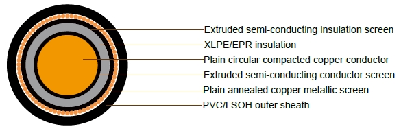
CONDUCTOR: Plain circular compacted copper to AS/NZS1125 Maximum Continuous Operating Temperature: 90°C
CONDUCTOR SCREEN: Extruded semi-conducting compound, bonded to the insulation and applied in the same operation as the insulation
INSULATION: Cross Linked Polyethylene (XLPE) – standard Ethylene Propylene Rubber (EPR) – alternative
INSULATION SCREEN: Extruded semi-conducting compound
METALLIC SCREEN: Plain annealed copper wire: 3kA for nominal 1 second(LIGHT DUTY) Plain annealed copper wire: 10kA for nominal 1 second(HEAVY DUTY)
SHEATH: Black 5V-90 polyvinyl chloride (PVC) – standard
Orange 5V-90 PVC inner plus black high density polyethylene (HDPE) outer – alternative Low smoke zero halogen (LSOH) – alternative
Technical Characteristics
LIGHT DUTY
| Nominal cond uctor area |
Maximum Cond uctor |
Cond. AC resistance at 50Hz and 90°C | Inductivereactance at 50Hz and 90°C | Insul ation resist ance at 20°C |
Conductor to screen capaci tance |
Maximum diaelectric stress | CurrentRatings | |||||
| DC resistance at 20°C | Trefoil or Flat touc hing |
flat spaced | Trefoil touc hing |
flat touc hing |
flat spaced | Unenc losed In Air |
Buried Direct | Buried In Ducts (c) | ||||
| mm2 | Ohm/km | Ohm/km | Ohm/km | Ohm/km | Ohm/km | Ohm/km | Meg Ohm. km |
µF x km | kV x mm | A | A | A |
| 16 | 1.15 | 1.47 | 1.47 | 0.161 | 0.176 | 0.222 | 14000 | 0.177 | 2.77 | 125 | 120 | 101 |
| 25 | 0.727 | 0.927 | 0.927 | 0.152 | 0.167 | 0.213 | 12000 | 0.198 | 2.65 | 163 | 154 | 129 |
| 35 | 0.524 | 0.668 | 0.668 | 0.147 | 0.163 | 0.208 | 11000 | 0.219 | 2.55 | 197 | 183 | 153 |
| 50 | 0.387 | 0.494 | 0.494 | 0.14 | 0.155 | 0.201 | 10000 | 0.242 | 2.46 | 237 | 216 | 181 |
| 70 | 0.268 | 0.342 | 0.342 | 0.135 | 0.15 | 0.196 | 8800 | 0.275 | 2.37 | 294 | 263 | 221 |
| 95 | 0.193 | 0.247 | 0.247 | 0.122 | 0.138 | 0.183 | 7700 | 0.314 | 2.3 | 359 | 313 | 264 |
| 120 | 0.153 | 0.196 | 0.195 | 0.117 | 0.133 | 0.178 | 7000 | 0.346 | 2.25 | 413 | 355 | 305 |
| 150 | 0.124 | 0.16 | 0.159 | 0.114 | 0.129 | 0.175 | 6400 | 0.374 | 2.21 | 470 | 397 | 341 |
| 185 | 0.0991 | 0.128 | 0.127 | 0.111 | 0.126 | 0.172 | 5900 | 0.407 | 2.17 | 539 | 447 | 384 |
| 240 | 0.0754 | 0.098 | 0.0973 | 0.106 | 0.122 | 0.167 | 5300 | 0.456 | 2.13 | 637 | 516 | 443 |
| 300 | 0.0601 | 0.0791 | 0.0781 | 0.104 | 0.119 | 0.165 | 4800 | 0.503 | 2.1 | 730 | 579 | 509 |
| 400 | 0.047 | 0.0631 | 0.0618 | 0.0988 | 0.115 | 0.161 | 4300 | 0.561 | 2.07 | 848 | 655 | 575 |
| 500 | 0.0366 | 0.0508 | 0.0489 | 0.097 | 0.112 | 0.158 | 3900 | 0.62 | 2.05 | 978 | 737 | 647 |
| 630 | 0.0283 | 0.0412 | 0.0389 | 0.0953 | 0.111 | 0.156 | 3500 | 0.694 | 2.02 | 1122 | 823 | 722 |
Cable Parameter
LIGHT DUTY
| Sectional Area of Conductor | Nom. Conductor Diameter | Nom. Insulation Thickness | Nom. Diamete Over insulation | Screen Area on Each core | No. and Diamter of Screened Wires | Nom. Diamete Over Screened Wires | Nom. Overall Diameter | Approx. mass |
| mm2 | mm | mm | mm | mm2 | no x mm | mm | mm | kg/100m |
| 16 | 4.8 | 3.4 | 12.8 | 16 | 28 x 0.85 | 14.1 | 20.3 | 58 |
| 25 | 5.8 | 3.4 | 13.8 | 20 | 36 x 0.85 | 15.3 | 21.5 | 73 |
| 35 | 6.8 | 3.4 | 14.8 | 20 | 36 x 0.85 | 16.3 | 22.5 | 84 |
| 50 | 8 | 3.4 | 16 | 20 | 36 x 0.85 | 17.6 | 23.8 | 98 |
| 70 | 9.6 | 3.4 | 17.6 | 20 | 36 x 0.85 | 19.0 | 25.2 | 121 |
| 95 | 11.5 | 3.4 | 19.4 | 20 | 36 x 0.85 | 20.7 | 26.9 | 148 |
| 120 | 13.1 | 3.4 | 21 | 20 | 36 x 0.85 | 22.1 | 28.3 | 174 |
| 150 | 14.5 | 3.4 | 22.4 | 20 | 36 x 0.85 | 23.5 | 29.7 | 202 |
| 185 | 16.1 | 3.4 | 24.1 | 20 | 36 x 0.85 | 25.3 | 31.5 | 240 |
| 240 | 18.5 | 3.4 | 26.5 | 20 | 36 x 0.85 | 27.6 | 33.8 | 298 |
| 300 | 20.7 | 3.4 | 28.9 | 20 | 36 x 0.85 | 29.8 | 36.2 | 360 |
| 400 | 23.6 | 3.4 | 31.8 | 20 | 36 x 0.85 | 33.2 | 39.8 | 449 |
| 500 | 26.5 | 3.4 | 34.7 | 20 | 36 x 0.85 | 36.5 | 43.3 | 550 |
| 630 | 29.9 | 3.4 | 38.4 | 20 | 36 x 0.85 | 40.1 | 47.1 | 690 |
Technical Characteristics
HEAVY DUTY
| Nominal cond uctor area |
Maxi mum Cond uctor |
Cond. AC resistance at 50Hz and 90°C | Inductive reactance at 50Hz and 90°C | Insulation resistance at 20°C | Conductor to screen capaci tance |
Maximum diaelectric stress | Current Ratings | |||||
| DC resist ance at 20°C |
Trefoil or Flat touc hing |
flat spaced | Trefoil touch ing |
flat touch ing |
flat spaced | Unencl osed In Air |
Buried Direct | Buried In Ducts (c) | ||||
| mm2 | Ohm/km | Ohm/km | Ohm/km | Ohm /km |
Ohm /km |
Ohm /km |
MegOhm. km | µF x km | kV x mm | A | A | A |
| 16 | 1.15 | 1.47 | 1.47 | 0.161 | 0.176 | 0.222 | 14000 | 0.177 | 2.77 | 125 | 120 | 101 |
| 25 | 0.727 | 0.927 | 0.927 | 0.152 | 0.167 | 0.213 | 12000 | 0.198 | 2.65 | 164 | 154 | 129 |
| 35 | 0.524 | 0.668 | 0.668 | 0.147 | 0.163 | 0.208 | 11000 | 0.219 | 2.55 | 200 | 184 | 154 |
| 50 | 0.387 | 0.494 | 0.494 | 0.14 | 0.155 | 0.201 | 10000 | 0.242 | 2.46 | 242 | 217 | 183 |
| 70 | 0.268 | 0.342 | 0.342 | 0.135 | 0.15 | 0.196 | 8800 | 0.275 | 2.37 | 298 | 262 | 221 |
| 95 | 0.193 | 0.247 | 0.247 | 0.122 | 0.138 | 0.183 | 7700 | 0.314 | 2.3 | 362 | 311 | 267 |
| 120 | 0.153 | 0.196 | 0.195 | 0.117 | 0.133 | 0.178 | 7000 | 0.346 | 2.25 | 413 | 351 | 301 |
| 150 | 0.124 | 0.16 | 0.159 | 0.114 | 0.129 | 0.175 | 6400 | 0.374 | 2.21 | 467 | 391 | 336 |
| 185 | 0.0991 | 0.128 | 0.127 | 0.111 | 0.126 | 0.172 | 5900 | 0.407 | 2.17 | 535 | 439 | 377 |
| 240 | 0.0754 | 0.098 | 0.0973 | 0.106 | 0.122 | 0.167 | 5300 | 0.456 | 2.13 | 627 | 503 | 432 |
| 300 | 0.0601 | 0.0791 | 0.0781 | 0.104 | 0.119 | 0.165 | 4800 | 0.503 | 2.1 | 715 | 561 | 493 |
| 400 | 0.047 | 0.0631 | 0.0618 | 0.0988 | 0.115 | 0.161 | 4300 | 0.561 | 2.07 | 824 | 630 | 553 |
| 500 | 0.0366 | 0.0508 | 0.0489 | 0.097 | 0.112 | 0.158 | 3900 | 0.62 | 2.05 | 943 | 702 | 616 |
| 630 | 0.0283 | 0.0412 | 0.0389 | 0.0953 | 0.111 | 0.156 | 3500 | 0.694 | 2.02 | 1072 | 777 | 681 |
Cable Parameter
HEAVY DUTY
| Sectional Area of Conductor | Nom. Conductor Diameter | Nom. Insulation Thickness | Nom. Diamete Over insulation | Screen Area on Each core | No. and Diamter of Screened Wires | Nom. Diamete Over Screened Wires | Nom. Overall Diameter | Approx. mass |
| mm2 | mm | mm | mm | mm2 | no x mm | mm | mm | kg/100m |
| 16 | 4.8 | 3.4 | 12.8 | 15.9 | 28 x 0.85 | 16.1 | 20.3 | 59 |
| 25 | 5.8 | 3.4 | 13.8 | 24.4 | 43 x 0.85 | 17.1 | 21.2 | 78 |
| 35 | 6.8 | 3.4 | 14.8 | 34.4 | 24 x 1.35 | 19.1 | 23.2 | 99 |
| 50 | 8 | 3.4 | 16 | 48.7 | 34 x 1.35 | 20.3 | 24.4 | 125 |
| 70 | 9.6 | 3.4 | 17.6 | 68 | 30 x 1.70 | 22.6 | 26.9 | 165 |
| 95 | 11.5 | 3.4 | 19.4 | 69 | 48 x 1.35 | 23.7 | 27.9 | 195 |
| 120 | 13.1 | 3.4 | 21 | 69 | 48 x 1.35 | 25.3 | 29.4 | 225 |
| 150 | 14.5 | 3.4 | 22.4 | 69 | 48 x 1.35 | 26.7 | 31.1 | 255 |
| 185 | 16.1 | 3.4 | 24.1 | 69 | 48 x 1.35 | 28.4 | 32.7 | 285 |
| 240 | 18.5 | 3.4 | 26.5 | 69 | 48 x 1.35 | 30.8 | 35.3 | 345 |
| 300 | 20.7 | 3.4 | 28.9 | 69 | 48 x 1.35 | 33.2 | 37.9 | 410 |
| 400 | 23.6 | 3.4 | 31.8 | 69 | 48 x 1.35 | 36.3 | 41.2 | 505 |
| 500 | 26.5 | 3.4 | 34.7 | 69 | 48 x 1.35 | 39.2 | 44.3 | 605 |
| 630 | 29.9 | 3.4 | 38.4 | 69 | 48 x 1.35 | 42.9 | 48.7 | 730 |
| 800 | 35.9 | 3.4 | 44.5 | 69 | 48 x 1.35 | 49 | 55 | 925 |